Morris Minor Owners ClubSeries MM Register |
Disclaimer:
Information on this website is given in good faith and whilst every effort is
made to check its accuracy anyone using said information does so at their own
risk, and liability cannot be accepted for loss or damage incurred through use
or misuse of aforementioned information.
1. Series MM Engine information (Torque settings, etc)
2. Morris Minor Paint Colour Codes
4. Ex Military Generator Engines
6. Front Suspension Stub Axle and Wheel Bolt Threads
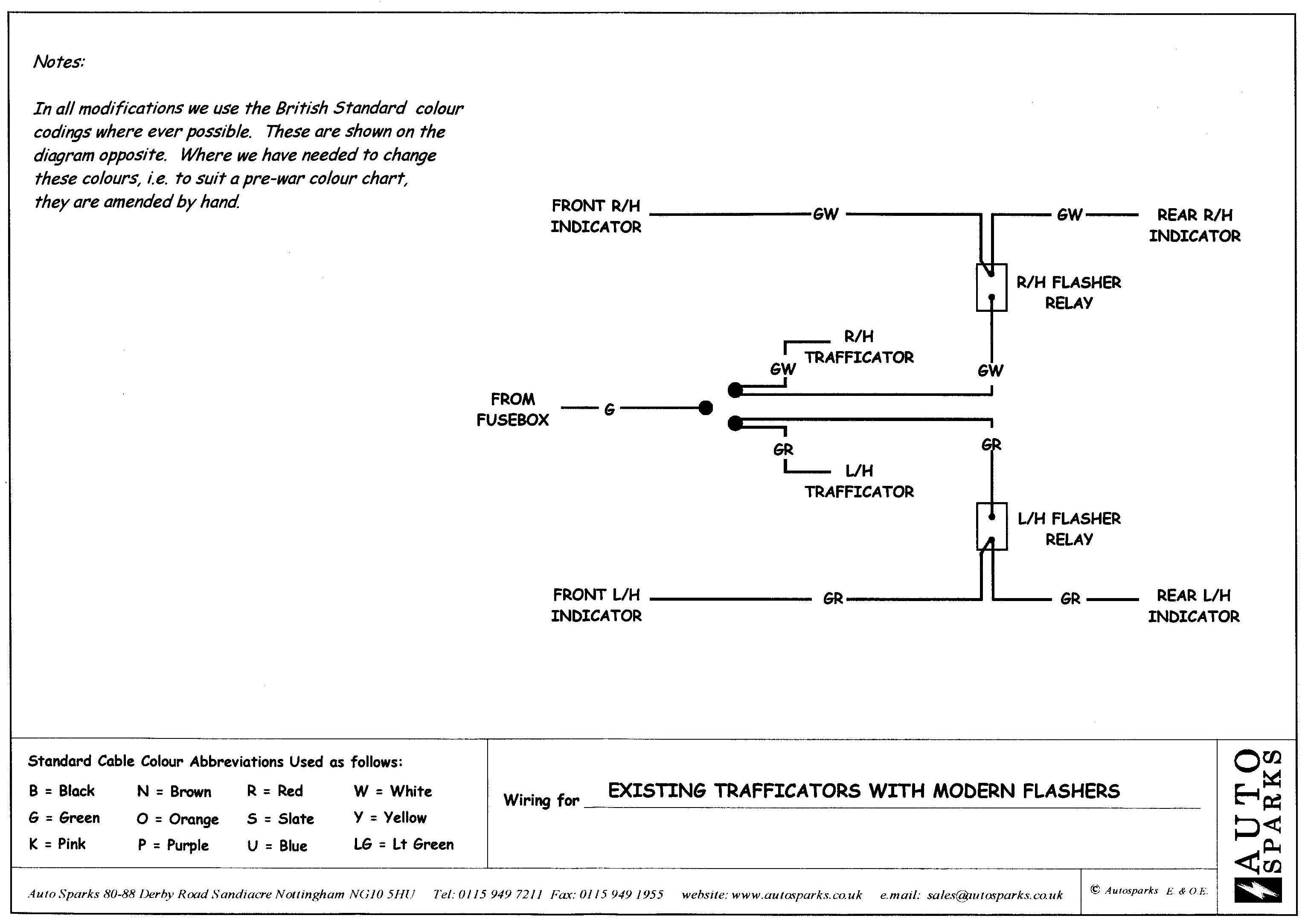
7. Combined Indicator and Trafficator Wiring Diagram
The torque settings for the Series MM engine are as follows:
| Cylinder Head Bolts | 44 lb. ft. |
| Main Bearing Bolts | 42 lb. ft |
| Big End Bolts | 27 lb. ft. |
| Flywheel Bolts | 42 lb. ft. |
| Gudgeon Pin Clamp | 12.5 lb. ft. |
| Manifold Nuts | 29 lb. ft. |
| Valve Clearances | 0.018 in. cold |
| Spark Plugs
Champion L10, L86YC NGK B6HS Autolite 425 |
0.022 in. |
| Points (DKYH4A dist.) | 0.014-0.016 in. |
| 40333A/40251E | 0.014-0.016 in. |
Cylinder Head Bolt Tightening Order:
|
11 5 13 7
3 8 |
Front of Engine
MORRIS MINOR PAINT COLOUR CODES
| COLOUR | BMC CODE | ICI REF. No. | DATE |
| BLACK | BLK 1 | N/A | 1948 - 1970 |
| PLATINUM GREY | N/A | 0123 | 1948 - 1950 |
| ROMAIN GREEN | N/A | 0095 | 1948 - 1950 |
| MAROON A | RD8 | 2473 | 1948 - 1950 1953 |
| MIST GREEN | N/A | 2383 | 1950 - 1952 |
| GASCOYN GREY | N/A | 2783 | 1950 - 1952 |
| THAMES BLUE | N/A | 2382 | 1950 - 1952 |
| CLARENDON GREY | GR6 | 2508 | 1952 - 1959 |
| EMPIRE GREEN | GN22 | 2509 | 1952 - 1956 |
| BIRCH GREY | GR3 | 2758 | 1952 - 1954 1956 - 1959 |
| SMOKE BLUE | N/A | 3306 | 1954 - 1955 |
| SANDY BEIGE | BE 15 | 6187 | 1955 - 1956 |
| DARK GREEN | GN12 | 5107 | 1956 - 1959 |
| SAGE GREEN | GN5 | 3116 | 1956 - 1959 |
| CREAM | YL5 | 2450 | 1956 - 1958 |
| TURQUOISE | BU6 | 2618 | 1956 - 1959 |
| PALE IVORY | YL1 | 3487 | 1958 - 1959 |
| FRILFORD GREY | GR5 | 3167 | 1959 - 1960 |
| PEARL GREY | GR10 | 3299 | 1959 - 1960 |
| CLIPPER BLUE | BU 14 | 3300 | 1959 - 1961 |
| SMOKE GREY | BU 15 | 3301 | 1959 - 1970 |
| YUKON GREY | GR4 | 2824 | 1960 - 1961 |
| OLD ENGLISH WHITE | WT3 | 2379 | 1960 - 1968 |
| PORCELAIN GREEN | GN17 | 5091 | 1960 - 1961 |
| DOVE GREY | GR26 | 3346 | 1961 - 1968 |
| ROSE TAUPE | GR27 | 6185 | 1961 - 1967 |
| ALMOND GREEN | GN37 | 3483 | 1961 - 1970 |
| HIGHWAY YELLOW | YL9 | 3480 | 1961 - 1962 |
| LILAC | RD17 | 3467 | 1961 |
| TRAFALGAR BLUE | BU37 | 6189 | 1962 - 1970 |
| MAROON B | RD23 | 6573 | 1967 - 1969 |
| PEAT BROWN | GR30 | 6198 | 1967 - 1970 |
| SNOWBERRY WHITE | WT4 | 3012 | 1967 - 1970 |
| BLUE ROYALE | BU38 | 5186 | 1969 - 1970 |
| FAUN BROWN | RD26 | 4860 | 1969 - 1970 |
| CUMULUS GREY | GR29 | 8780 | 1969 - 1970 |
| CONNAUGHT GREEN | GN18 | 3302 | 1969 - 1970 |
| GLACIER WHITE | NMA/059 | 4309 | 1969 - 1971 |
| BERMUDA BLUE | BU40 | 2843 | 1969 - 1970 |
| WHITE | NAB/206 | 3738 | 1969 - 1970 |
| AQUA | JMA/060 | 7932 | 1970 - 1971 |
| LIMEFLOWER | HMA/029 | 7968 | 1970 - 1971 |
| BEDOIN | SAA/004 | 7855 | 1970 - 1971 |
| TEAL BLUE | JMC/018 | 7918 | 1970 - 1971 |
|
WHEELS BODY
COLOUR ON SERIES MM& SII SILVER ON LATE 1098 |
|||
|
SERIES
MM ENGINE AND GEARBOX BLUE/GREY |
|||
|
A
SERIES ENGINE TRY FORD LAUREL GREEN |
XSC | 1137 | |
| *MM DASHBOARD GOLD | 2RB8 |
* Contact Registrar for suppler
| COLOUR | BMC CODE | ICI REF. No. | DATE |
| AZURE BLUE | N/A | 7660 | 1953 - 1956 |
| PERSIAN BLUE | BU39 | 2351 | 1968 - 1971 |
| EVERGLADE GREEN | GN42 | 7152 | 1968 - 1971 |
| DAMASK RED | CMA/099 | 4808 | 1968 - 1971 |
| FLAME RED | CMB/061 | 3442 | |
| PEONY RED | 1968 - 1971 | ||
| ANTELOPE | BLVC007 | 7984 | |
| POST OFFICE MID BRONZE GREEN | N/A | 0099 | |
| TELECOM YELLOW | FMA/1011 | JP89 | |
| POSTAL SERVICES RED | CMC/1038 | 8032 | |
| POLICE WHITE | NMB/1024 | HT49 | |
| POLICE BERMUDA BLUE | BU40 | 2843 | |
| ARMY OLIVE GREEN | N/A | 3737 | |
| RAF BLUE GREY | N/A | 0242 | |
| NAVY BLACK | BLK1 | N/A | |
| WIMPEY HOMES YELLOW | N/A | JE69 | |
| CO-OP BLUE | N/A | AD36 | |
| CURRYS WEMBLEY BLUE | N/A | GJ29 |
A quantity of ex military generator engines from various
sources has been coming onto the market over the last few years, and whilst they
provide a useful supply of engines for the Series MM Minor, their fitting is not
quite as straightforward as may at first appear.
The engine is basically of the USHM3 type of block as
fitted to the later Series MMs and was used as an auxiliary generator engine in
the Centurion tank when the vehicle was stationary.
The useable parts of the engine are confined to the
cylinder block, crankshaft, pistons, timing gear, camshaft, and valve assembly
and so a donor engine will be required to supply the remaining parts.
The engines may vary in detail as to the fitting of
external components but I shall attempt to go through the various points to be
noted when fitting these engines.
Various claims are made as to the condition of these
engines, such as very little used, recently overhauled etc. From
experience a precautionary strip down and inspection is recommended, mine was
heavily coked up and the pistons were fitted the wrong way round.
The engines are often supplied with extra external
pipework and bolt on accessories which will need to be removed.
The cylinder head is of a completely different design and
will be of no use in a car; however if you know someone with a President tractor
or a side valve Vedette marine engine they may be grateful for a spare cylinder
head. In order to fit the correct cylinder head of either the early or later
type the centre and right hand rows of cylinder head studs will need to be
changed for those of the correct length. The distributor and spark plugs will
need to be changed for the correct type and the distributor jack shaft is also a
different length. An accelerator cable stop and a heater tap or blanking plug
will also be required.
The flywheel is drilled to fit a power take-off and
is fitted with an 80T starter ring instead of the 102T ring so a donor flywheel
and clutch assembly will be required.
At the other end of the engine the oil filler pipe is
normally fitted to the timing chain cover and as this will not fit under the
radiator header tank it will require changing for the correct type of cover or
the filler removed and the blanking plug from the side of the engine fitted. The
crankshaft pulley is also different to the car version. A blanking plug is
fitted in the location of the car oil filler pipe.
The generator engine dip stick is located on the manifold
side of the engine but will probably foul the car manifold and will therefore
need to be removed and the hole plugged, and the blanking plug on the other side
of the engine punched out to fit the car dip stick. The generator dip stick will
not be correctly calibrated.
Whilst on the carburettor side of the engine the tappet
cover is different, having no breather holes and a recirculating vent pipe. The
oil pressure pipe can be fitted in place of the oil pressure sensor and the oil
filter can be fitted in place of the external filtering union. The car manifold
and carburettor will replace the generator system. Towards the front of the
engine is a large bolt with an extended thread. As this is tapped directly into
the main oil gallery it should be left in place unless a blanking plug of the
correct thread is available.
At the front of the engine the standard blanking plate is
fitted and can be refitted after an inspection of the water chamber for sludge
if a water pump is not to be used.
The water jacket is not fitted with a dynamo mounting
bracket. It is however an iron casting, unlike the alloy car water jacket which
is prone to corrosion, and if there is no sign of leakage it would be wise
to leave it in place unless a good alloy casting is available. If fitting the
later type of cylinder head a dynamo mounting bracket can be made from dexion or
similar and hung from the front cylinder head studs. Depending on whether or not
a water pump is to be fitted, the correct inlet pipe/drain tap will be required
on the side of the block.
If removing the crankshaft it will be noted that it is
different from the unit fitted to the car, having no oil thrower scroll at its
rear end, instead having an oil seal. The rear main bearing cap is also
different. The correct oil seal will need to be fitted or one made. The
crankshafts are not interchangeable between the generator and car engines. As
the engine was not fitted to a gearbox it is probable that the drive gear bush
into which the front shaft of the gearbox fits will be missing.
What may not be obvious is that the sump is of a different
design, visible on the outside by having the drain plug on the left side instead
of centrally underneath. Inside the sump has no reservoir casting for the oil
pump pick-up. The rear pair of sump bolts are shorter and the baffle plate has
no dip stick hole.
The oil pump is a robust looking unit with a filter on the
pick-up, however it is designed for static running and suffers from oil pressure
loss when cornering in a car. As with the cylinder head, the oil pump may have
marine applications.
Car Engine Crankshaft With Scroll

Generator Engine Crankshaft Without Scroll

M. J. Perry
Ammended 01 05 10
To convert Series MM cars to Minor 1000 swivel pin assemblies.
This conversion involves a once only modification to the Series MM hub.
The inner bearing is replaced by bearing RHP6205 and the outer bearing by RHP6303. These bearings fit exactly onto the Minor 1000 stub axle. The MM hub then needs machining to take the very slightly larger outer diameters of the new bearings. When machining out the bearing housings care should be taken to machine exactly to the original bearing abutment faces so that the bearings retain their original separation along the stub axle.
Next obtain a Morris 1000 bearing spacer (distance piece) and have this machined to the same length as the MM spacer by removing metal from the thicker end.
Assemble the hub, bearings, spacer and oil seal normally and pack with grease.
Refit the MM back plate and brakes onto the new swivel pin assembly. Fit the hub assembly onto the stub axle. A steel washer 2-3mm thick with a 17mm (11/16) diameter hole will be needed as the 17mm portion of the stub axle may slightly protrude through the centre of the outer bearing. Use Minor 1000 axle nut and split pin. Tighten up as normal.
A word of warning
A previous contributor Tech. Tips has described a different method of converting Series MMs to the use of Minor 1000 swivel pins assemblies. This involves the removal of the larger stub axle and machining the outer portion from 25mm to 7/8 diameter.
This is bad engineering practice. The point of change of diameters is subject to maximum bending moment and the introduction of this stress raiser is likely to cause eventual metal fatigue at this point resulting in the breaking off of the stub axle, so losing the wheel and brakes.
Parts Required
Minor 1000 left and right hand swivel pins and hub nuts
RHP 6205 inner bearings x2
RHP 6303 outer bearings x2
Minor 1000 bearing spacers x2
Steel washers 2-3 mm thick with 17 mm hole x2
How not to do it: Click HERE
Front Suspension Stub Axle and Wheel Bolt Threads
By Graham Holt
I have studied available written references and practical examples of Swivel pin
/ stub axle and brake drum assemblies in my possession and the following is my
interpretation of what happened when' regarding the various changes carried
out on the Hubs, Stub Axles, Hub Retaining Nuts and Wheel Bolts during
production of the Series 'MM' and early Series 11 Minors.
I have used the Morris Motors Service Parts List, Issue 3, date Jan 1953,
c / w Supplements 1 to 4 dated Feb 1953 to Aug 1953 as my main information source. I also appreciate the relevant information in Ray Newells book 'Original Morris Minor'
This is a simple version of sequence of
changes
---------------------------------------------------
1. From start of production the
Series 'MM' used BSF threads for stub axle retaining nut and wheel bolts.
Stub Axle thread:- 1/2" x 16TPI (BSF).
Castle Nut requires <7/16" Whit/ 1/2" BSF> Socket size.
Wheel Bolt thread:- 7/16" x 18TPI (BSF). Use < 3/8" Whit /
7/16" BSF> Socket size.
1a. There was a change to the hub and stub
axle when a larger outer wheel bearing was introduced (at car no RHD 31790 / LHD
12338 - date c Dec 1949) but the wheel bolts and axle retaining nut remained the
same.
This was the set up on my own MM car
no.69721
2. Major Change (at car RHD
131858 / LHD 126725 - date c Jan 1952) was the introduction of UNF threads to
the Wheel Bolts and larger axle thread size. Stub Axle thread:- 5/8 x
14TPI (BSF)
Castle Nut requires <1A/F> Socket size
Wheel Bolt thread:- 7/16 x 20TPI (UNF).
Use <5/8A/F> Socket size
Points worthy of note here are:-
The thread of the Stub Axle/Hub Retaining Nut was changed to 5/8" BSF, but
was given a UN Size Hexagonal head. (I believe this may possibly be due to a
large qty of stub axles with BSF threads being already available and the Hex
Size was introduced to use these up and to meet the requirement of export
market, although it meant having a "Special" nut.
The Wheel Retaining Bolts were given the small Hex Head. (Perhaps the Drawing
Office had just been introduced to UN fixings and someone didn't check the UN
hex size for comparison with BSF hex size ! = just my theory). I believe that
the small hex size caused problems in use causing wear in the wheel holes
Perhaps, also, the smaller hex size made the different bolt more distinguishable.
The rear axle hubs, the spare wheel retaining
clamp bolt and the wheel brace / hubcap lever supplied with each car, were also
amended to suit, at this time.
This was the set-up on the 'MM' which I stripped for spares in 1976 - Car No
173726. I can confirm that the rear axle and wheel bolt details agree with the
above. I believe that the car was quite original. (I did not acquire the front
hubs though!).
I regret that my available information does
not include much on the early Series II, for comparison. I note that Ray
Newells book does say that the wheel bolt was given a larger hex size in
March 1953 at car no 184760, after 'MM' production had ceased.
Size quoted is 0.705" / 0.710" A/F, which equates to a 3/8Whit /
7/16BSF Hex size !!!! So I presume that early Series 11's went back to same
size as early Series 'MM's
Additional Notes by Michael Perry
3. Minor 1000 Suspension introduced on the Series II Traveller, car no. 216901. Swivel Pins distinguished by blank circular boss above steering arm.
Axle thread is 5/8 x 18TPI (UNF), usually written as 5/8 - 18 UNF)
Castle Nut requires 15/16 A/F Socket size
Wheel bolts were changed to wheel nuts.
Thread:- 3/8 x 24TPI (UNF), use 3/8Whit / 7/16BSF Socket size
There is a set of instructions in Tech. Info for converting Series MM brake drums to fit M1000 swivel pins
I would recommend that the thread detail (i.e.:- external diameter and TPI = threads per inch) are checked for every enquiry because early Minors had a number of versions on a theme as regards axle threads as well as axle lengths.
And anything may have been fitted to any car of any year as a get out of trouble quick fix during its life time, only to cause problems years later
Especially do not trust the hex size of any bolt to define its thread.
Table of appropriate axle thread sizes
(a) ½ BSF = 16TPI
(b) 5/8 BSF = 14TPI
(c) ½ UNF = 20TPI (½ - 20 UNF)
(d) ½ UNC = 13TPI (½ - 13 UNC)
(e) 5/8 UNF = 18 TPI (5/8 - 18 UNF)
(f) 5/8 UNC = 11TPI (5/8 - 11 UNC)
This
information is extracted from Zeus Data Chart and Reference Tables
Graham Holt.
Combined Indicator and Trafficator Wiring Diagram - CLICK HERE